Install the TouchBase Gen6 Protective Enclosure
TouchBase Gen6 Protective Enclosure
The TouchBase Gen6 Protective Enclosure protects your TouchBase time clock from dirt, dust, and water spray. The Protective Enclosure is not intended for use in outdoor locations directly exposed to the elements. For information on a time clock designed for outdoor environments, please contact your UKG representative.
Install the TouchBase Gen6 Protective Enclosure
To install the UKG ProTouchBase Gen6
Protective Enclosure, you need the following tools and hardware:
-
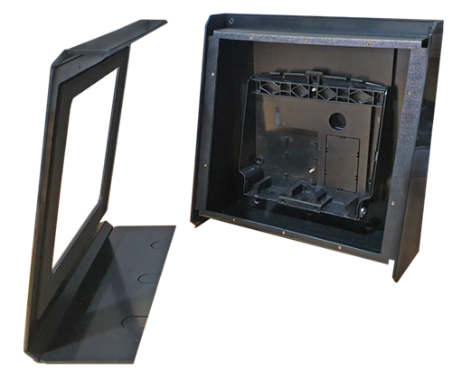
Verify that the enclosure kit includes the following components:
- 1x protective enclosure front panel
- 1x protective enclosure body
- 1x lockless clock mounting backplate
- 1x rubber grommet
- 10x M4 front fixing screws
-
Use one of the following methods to route the cables:
- Route the cables from the back or wall entry (recommended). To access the back or wall, pop out
the rear breakout tab. Fit a rubber grommet to the hole once it has been punctured for
cable ingress.
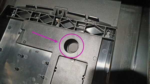
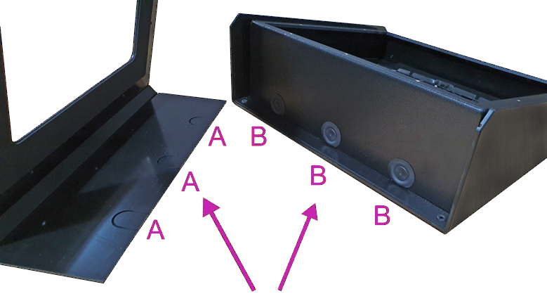
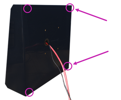
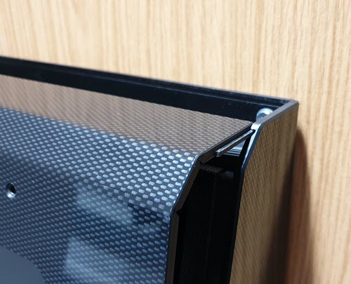
- Route the cables from the bottom of the enclosure body. Break or cut one or more of the plastic
tabs on the bottom of the front panel (labeled A in the following image). Then,
puncture the corresponding grommets (labeled B in the following image) for cable
ingress.
- Route the cables from the back or wall entry (recommended). To access the back or wall, pop out
the rear breakout tab. Fit a rubber grommet to the hole once it has been punctured for
cable ingress.
-
Mount the enclosure using a VESA standard mount or by directly mounting to a
wall.
Note To use a VESA standard mount, refer to the instructions provided with your VESA mounting adapter (not provided by UKG).
To mount directly to the wall, use the following steps:
-
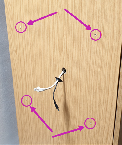
Using a level, mark the four corner mounting points on the wall and drill pilot
holes. Depending on your mounting surface, you may need to install additional mounting
hardware such as drywall anchors.
-
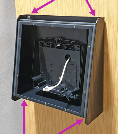
Pull the cables through the cutout on the enclosure and the smaller backplate. Seal
the grommet into place.
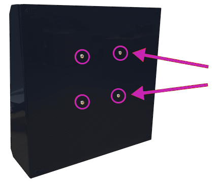
-
Align the enclosure and tighten the four screws until the unit is firmly in
place.
Note The inner backplate does not have a locking mechanism. The front panel seals the unit inside.
-
Using a level, mark the four corner mounting points on the wall and drill pilot
holes. Depending on your mounting surface, you may need to install additional mounting
hardware such as drywall anchors.
-
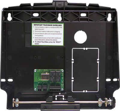
Optionally, mount the relay module to the backplate. Refer to the Relay Module Field
Installation Instructions guide for more information about wiring and installing the relay
module.
-
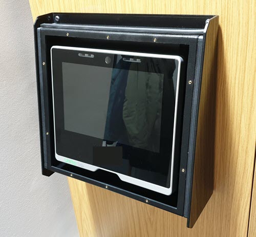
Align the terminal’s top edge with the enclosure’s top inner edge at a 45-degree angle.
Rotate into position as you would with fitting the standard unit to the standard back
box.
Once seated in place, the terminal should fit with the touch screen parallel to the front enclosure.
-
Align the front panel’s bottom tongue with the enclosure’s bottom grooves on both
sides.
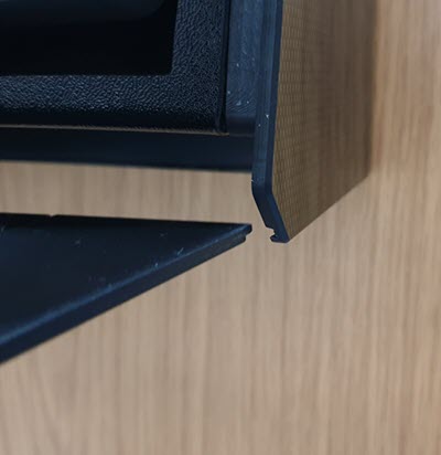
Once aligned, slide the front panel halfway in.
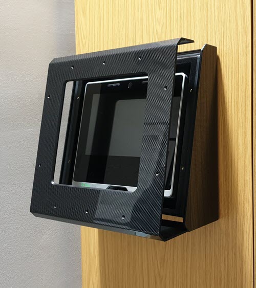
-
Align the front panel’s top tongue with the enclosure’s top groove. Once aligned, slide
the front panel fully back.
-
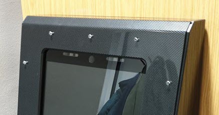
Fit the ten M4 front fixing screws into the countersunk holes. Partially tighten the
screws using low torque in a diagonal pattern across the front.
© UKG Inc. All rights reserved. For a full list of UKG trademarks, visit www.ukg.com/trademarks. All other trademarks, if any, are the property of their respective owners. No part of this document or its content may be reproduced in any form or by any means or stored in a database or retrieval system without the prior written authorization of UKG Inc. (“UKG”). Information in this document is subject to change without notice. The document and its content are confidential information of UKG and may not be disseminated to any third party. Nothing herein constitutes legal advice, tax advice, or any other advice. All legal or tax questions or concerns should be directed to your legal counsel or tax consultant.
Liability/Disclaimer
UKG makes no representation or warranties with respect to the accuracy or completeness of the document or its content and specifically disclaims any responsibility or representation for other vendors’ software. The terms and conditions of your agreement with us regarding the software or services provided by us, which is the subject of the documentation contained herein, govern this document or content. All company, organization, person, and event references are fictional. Any resemblance to actual companies, organizations, persons, and events is entirely coincidental.
Links to Other Materials: The linked sites and embedded links are not under the control of UKG. We reserve the right to terminate any link or linking program at any time. UKG does not endorse companies or products to which it links. If you decide to access any of the third-party sites linked to the site, you do so entirely at your own risk.